
Aircraft systems have gotten complicated with all the technical jargon flying around. Today, I’ll break down what’s really happening beneath the floor panels and behind the cockpit walls.
Propulsion Systems
Jet engines convert fuel into forward motion through carefully controlled combustion and airflow management. Pretty simple concept, remarkably complex execution.
How Turbofan Engines Work
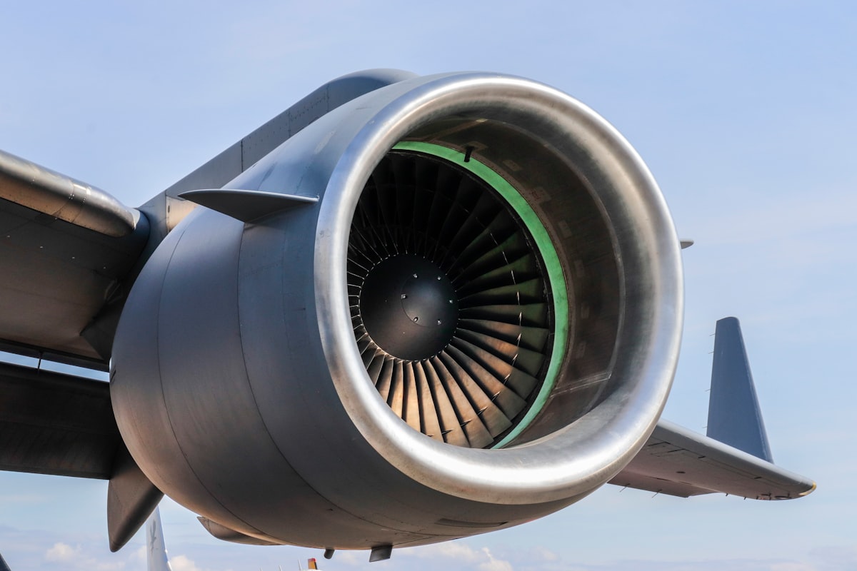
Commercial jets use high-bypass turbofan engines. Most of the air—about 80% of total thrust—flows around the engine core rather than through it. That big fan up front does the heavy lifting. The core engine with its compressor, combustor, and turbines generates the rest while powering the fan.
Here’s the process: Air enters through the fan, which compresses it slightly before splitting into bypass and core flows. Core air goes through multiple compressor stages that crank pressure up to 30-40 times atmospheric. This compressed air enters the combustor where fuel injection and ignition create temperatures over 2,000°F.
Hot combustion gases expand through turbine sections that extract energy to drive the compressor and fan. Remaining energy accelerates exhaust rearward—Newton’s third law in action. Bypass air merges with core exhaust at the exit, creating combined thrust.
Engine Management Systems
FADEC (Full Authority Digital Engine Control) runs modern jet engines, constantly adjusting fuel flow, variable geometry, and other parameters. These systems monitor hundreds of parameters and make thousands of adjustments per second—stuff human pilots couldn’t possibly manage manually.
FADEC protects engines from damage by limiting operations that could cause overtemperature, overspeed, or other problems. When pilots push the thrust levers forward, FADEC handles the actual response to achieve requested thrust safely. This automation has dramatically improved reliability while cutting pilot workload.
Flight Control Systems
Flight controls translate your pilot’s stick movements into aerodynamic forces that steer through the sky.
Primary Flight Controls
Three types of primary controls manage movement around three axes. Ailerons on the outer wings control roll by moving opposite directions—one up, one down. Elevators on the horizontal tail control pitch, pointing the nose up or down. The rudder on the vertical tail controls yaw, swinging the nose left or right.
On fly-by-wire aircraft, electrical signals replace mechanical cables between cockpit and control surfaces. Flight computers interpret pilot inputs and command hydraulic actuators to move surfaces. This setup enables envelope protection—computers can limit inputs that would exceed safe aircraft parameters.

Secondary Flight Controls
Flaps and slats reshape the wing for different flight phases. Trailing edge flaps extend downward and backward during takeoff and landing, increasing wing area and curve to generate more lift at lower speeds. Leading edge slats extend forward, preventing airflow separation that would cause stall at high angles.
Speed brakes (spoilers) pop up from the upper wing surface to increase drag and reduce lift. Pilots use them for descent control, slowing down, and helping brakes after landing. Some aircraft have ground spoilers that deploy automatically at touchdown, pushing weight onto the wheels for better braking.
High-Lift Systems
Takeoff and landing need slow enough speeds for runway ops while generating enough lift to stay airborne. High-lift systems—flaps, slats, and sometimes blown flaps or circulation control—dramatically boost lift coefficient, enabling safe speeds that would stall a clean wing.
Different flap settings serve different conditions. Takeoff typically uses partial extension for adequate lift with acceptable drag. Landing uses max extension to achieve lowest approach speeds, reducing runway needs and improving stopping.
Hydraulic Systems
Hydraulic fluid under high pressure powers most systems needing significant force—flight controls, landing gear, brakes.
System Architecture
Commercial aircraft typically run three independent hydraulic systems for redundancy. Each includes pumps (engine-driven, electric, or both), reservoirs, distribution lines, and actuators. If one fails, the others can still power essential functions, though some capabilities might be reduced.
That’s what makes hydraulic power impressive for us aviation types—operating at 3,000 PSI, a flight control actuator the size of a soda can generates enough force to move control surfaces against aerodynamic loads at 500 mph.
Backup Systems
Electric motor-driven pumps provide backup if engine-driven pumps fail. Some aircraft carry Ram Air Turbines (RATs)—small propellers that deploy into the airstream to generate emergency hydraulic and electrical power. RATs provide enough for essential flight controls even with all engines out.
The 787 takes a different approach, using electric actuators for many functions traditionally hydraulic. This “more-electric” architecture saves weight and complexity while improving reliability. Future designs will likely continue this trend.
Electrical Systems
Modern aircraft depend on extensive electrical systems powering avionics, lighting, entertainment, and increasingly, flight-critical stuff.
Power Generation
Engine-driven generators produce most electrical power—typically 115-volt, 400-hertz AC that transformers and rectifiers convert to various voltages for different systems. The 787 generates 1.45 megawatts—enough to supply a small neighborhood—primarily for its electric-driven systems.
APUs (Auxiliary Power Units), small gas turbines in the tail, generate electrical power and compressed air when main engines aren’t running. APUs allow cabin conditioning and systems at the gate without external equipment, improving comfort and flexibility.
Distribution and Protection
Distribution systems route power through multiple buses with automatic switching that maintains critical system power even if generators fail. Circuit breakers and solid-state devices prevent damage from shorts or overloads.
Batteries back up essential instruments and communications if all generators fail. Lithium-ion batteries on newer aircraft offer better energy density than traditional nickel-cadmium, though thermal management adds complexity.
Environmental Control Systems
At cruise altitude, unprotected humans would pass out quickly from low pressure and extreme cold. Environmental systems maintain comfortable conditions throughout flight.

Pressurization
Cabins maintain pressure equivalent to about 6,000-8,000 feet even when flying at 35,000-40,000 feet. Bleed air from engine compressors (or electrically compressed air on the 787) flows into the cabin while outflow valves regulate pressure by controlling how fast air escapes.
The pressure difference between inside and outside at cruise approaches 9 PSI, creating enormous fuselage stress. This repeated loading every flight requires careful structural design and maintenance to prevent fatigue failures.
Temperature Control
Air conditioning packs cool hot bleed air using air cycle machines—basically reverse jet engines that extract heat from airflow. Cooled air mixes with recirculated cabin air before distribution through overhead vents.
Passengers complain about temperature variations. The challenge is balancing thermal loads that vary throughout the cabin—body heat from passengers, solar heating on one side, cold walls adjacent to -60°F outside air. Zone control systems try to balance these factors with varying success.
Air Quality
HEPA filters remove 99.97% of airborne particles from recirculated air, cleaner than most buildings. Complete cabin air exchange happens every 2-3 minutes, far exceeding ventilation standards for other indoor spaces. Filtration plus rapid exchange minimizes disease transmission despite close passenger proximity.
Navigation Systems
Modern navigation provides position accuracy within meters, enabling precise routing and approaches that earlier pilots couldn’t imagine.
GPS and Inertial Navigation
GPS receivers provide primary navigation, calculating position from multiple satellite signals. But GPS can be jammed or spoofed, so aircraft also carry Inertial Reference Systems that calculate position from accelerometers and gyroscopes, maintaining capability if GPS goes down.
IRS accuracy degrades over time from accumulated sensor drift, so modern systems blend GPS and inertial data for optimal accuracy and reliability. Combined systems perform better than either alone while maintaining capability if one fails.
Radio Navigation
VOR stations transmit signals that aircraft receivers convert to bearing information. Though GPS has largely replaced VOR for en route nav, these ground aids remain important as backups and for certain approaches.
ILS (Instrument Landing Systems) provide precise guidance in low visibility. Transmitters generate signals that cockpit instruments display as crosshairs—keep them centered to fly precisely down the glideslope. Category III ILS enables landings with near-zero visibility, though aircraft and crew need specific certification.
Flight Management Systems
Flight Management Computers combine nav data, performance models, and airline preferences to calculate optimal routes, speeds, and altitudes. Pilots program origin, destination, and route, then FMC commands autopilot and autothrottle to fly the profile.
FMCs continuously update calculations based on actual winds, weight, and conditions. They optimize fuel consumption, predict arrivals, and manage step climbs to more efficient altitudes as fuel burns off.
Communication Systems
Aircraft maintain constant contact with ATC and airline operations through multiple redundant systems.
Voice Communications
VHF radios provide primary air-to-ground communication within line of sight—typically 200-300 miles at cruise altitude. Multiple VHF transceivers provide redundancy, and pilots monitor multiple frequencies simultaneously for traffic and controller instructions.
HF radios enable communication over oceanic areas beyond VHF range. HF signals bounce off the ionosphere for beyond-line-of-sight coverage, though quality varies with atmospheric conditions.
Data Communications
ACARS transmits data between aircraft and airline operations. Flight plans, weather, maintenance reports, and operational messages flow through ACARS, reducing voice workload and providing permanent records.
CPDLC (Controller-Pilot Data Link) enables text-based ATC communication, supplementing voice for routine clearances. Pilots receive instructions on displays, acknowledge with button presses, and aircraft automatically tune frequencies and adjust routes. CPDLC reduces radio congestion and eliminates readback errors.
Satellite Communications
SATCOM provides voice and data anywhere on Earth, enabling continuous connectivity over oceans and polar regions. Passengers get in-flight WiFi through SATCOM while pilots use satellite links for weather updates, operations, and emergency coordination beyond VHF range.
Landing Gear Systems
Landing gear absorbs landing impact, supports aircraft weight, and enables braking and steering.
Gear Design
Tricycle arrangements—two main gear under wings plus nose gear—dominate commercial aviation. Main gear absorb loads through oleo struts that compress hydraulic fluid and nitrogen, dissipating energy smoothly. Multiple wheels distribute weight and provide braking redundancy.
Retraction dramatically reduces drag for cruise efficiency. Hydraulic actuators retract gear into wheel wells where doors close for aerodynamic smoothness. Extension normally uses hydraulics but includes free-fall backup—gravity drops the gear if hydraulics fail.
Braking Systems
Carbon brakes withstand temperatures over 1,500°F during max braking, converting kinetic energy to heat. Antiskid systems prevent lockup by rapidly modulating brake pressure—like automotive ABS but far more sophisticated.
Autobrake systems automatically apply predetermined pressure after touchdown, reducing workload and ensuring consistent stopping. Pilots select settings before landing based on runway length, conditions, and desired exit.
Ice Protection Systems
Ice accumulation can catastrophically degrade performance, so extensive systems prevent or remove it during icing conditions.
Anti-Ice and De-Ice Methods
Hot bleed air flows through passages in wing leading edges, engine inlets, and other critical surfaces, preventing formation. These anti-ice systems run continuously in icing conditions, consuming bleed air that slightly reduces efficiency but ensures safety.
Pneumatic de-ice boots on some aircraft periodically inflate to crack off accumulated ice. This uses less bleed air than continuous heating but allows some buildup between cycles. Boots remain common on turboprops and some older jets.
Ice Detection
Detectors on the fuselage sense accumulation and alert pilots or activate protection automatically. Visual identification remains important since ice can accumulate in conditions that don’t always trigger warnings.
Fire Protection Systems
Multiple systems detect and suppress fires in engines, cargo holds, and other areas.
Engine Fire Detection and Suppression
Dual-loop detection systems in engine nacelles sense heat, triggering warnings that prompt pilots to shut down and discharge extinguishing agents. Halon or replacement agents flood the nacelle quickly. Each engine typically has two extinguisher bottles for a second attempt if needed.
Cargo Fire Suppression
Smoke detectors alert pilots to cargo fires they can’t see. Suppression systems discharge agents to lower oxygen and cool the fire, controlling it until landing. Protection has improved significantly following tragic accidents from uncontrolled cargo fires.
The Integrated Aircraft
These systems don’t operate in isolation—they’re integrated through shared data networks, common displays, and carefully designed interactions. Understanding individual systems provides foundation for appreciating how modern aircraft achieve remarkable safety and efficiency through sophisticated integration.
Next time you board a commercial flight, consider the engineering surrounding you. Thousands of components working together seamlessly enable routine flights that would have seemed miraculous decades ago. Modern aircraft truly represent the pinnacle of integrated systems engineering.


Stay in the loop
Get the latest flighttechtrends updates delivered to your inbox.