Why G3X Touch Installs Go Wrong More Than You’d Think
G3X Touch installation has gotten complicated with all the conflicting advice flying around. Forums say one thing, the manual says another, and your buddy who built a Sling 4 last year swears by a third approach. As someone who’s crawled through more experimental avionics bays than I care to count, I learned everything there is to know about how these installs fail — and why they fail quietly instead of loudly. Today, I will share it all with you.
The Garmin G3X Touch has become the default glass cockpit choice for experimental and Light Sport builders. It’s affordable compared to certified glass, scales cleanly from a single display to a full redundant setup, and the compatible sensor ecosystem keeps growing. That same flexibility, though, is exactly what creates installer pitfalls. I’ve walked avionics bays where a builder nailed the rigging, nailed the engine work, and then discovered their G3X install was hemorrhaging data or throwing phantom errors during ground power checks. That’s what makes the G3X endearing to us builders — and occasionally maddening.
Most mistakes don’t show up on the bench. They surface during ground testing or — worse — on first flight. A magnetometer placed too close to a landing gear actuator works fine at idle. Fails spectacularly on final. A CAN bus termination resistor installed in the wrong location reads clean during a 5-minute power-on check, then drops devices intermittently after 20 minutes of taxi. So, without further ado, let’s dive in.
Magnetometer Placement That Kills Compass Accuracy
But what is the GMU 11 or GMU 22 magnetometer, really? In essence, it’s the unit responsible for your compass heading. But it’s much more than that — it’s the foundation your autopilot and attitude system trust when everything gets confusing up there.
And it’s absurdly sensitive to its environment. Placed wrong, it doesn’t fail loudly. It fails quietly, feeding slightly incorrect heading data that accumulates into a creeping compass error you might not catch until you’re in actual IMC.
I learned this firsthand in a Zenith 801 build. The builder had mounted the GMU 22 on the tail boom — seemed logical, right? As far from electrical noise as you can get. Except it sat directly above the landing gear torque tube. During gear extension and retraction, the magnetic field shifted. The compass card rotated. The autopilot, synced to that compass, wanted to correct. Nothing catastrophic. Just wrong enough to be dangerous in instrument conditions.
Keep the magnetometer at least 24 inches away from control cables, transponder antennas, engine wiring bundles, and any moving metal. Landing gear actuators, trim motors, electric flap drives — all offenders. Vertical separation counts too. Heat from the avionics bay drifts upward and can skew calibration over time. If your fuselage is tight, mount it outside the cabin entirely if your airframe allows.
Once you’ve positioned the unit, run the magnetometer calibration procedure — at least if you want accurate heading data in anything beyond VFR cruise. Power up the G3X, navigate to System Setup, run the in-flight calibration. The display walks you through slow turns in all axes. Watch the calibration quality percentage. Anything below 95 percent is a red flag. I’ve seen installs stuck at 78 percent. That told us immediately the magnetometer was either placed wrong or mounted near ferrous metal. We relocated it six inches. Ninety-eight percent on the second try.
One more detail: don’t bundle the external magnetometer’s twisted-pair cable with power wiring. It picks up noise. It drifts. Route it separately, even if that costs you an extra 30 minutes in the avionics bay. Don’t make my mistake.
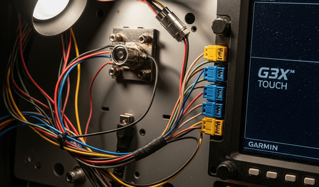
CAN Bus Wiring Errors That Cause Intermittent Faults
The Controller Area Network — CAN bus — is how your G3X Touch talks to the GSU 25, engine monitor, autopilot, and every other networked peripheral. Get it wrong and you don’t get a hard failure. You get devices vanishing and reappearing on the system page. Red X marks during taxi that clear themselves mid-flight. Builders calling their avionics shop in a panic because the engine monitor dropped offline 40 minutes into their first cross-country.
Three mistakes kill more CAN bus installs than anything else: termination resistor placement, topology confusion, and wire gauge mismatch.
Probably should have opened with this section, honestly. Termination errors are that common. Every CAN bus needs a 120-ohm termination resistor at each end of the network. Five devices on your bus? Resistors go on the last device in line at each physical end — not the middle, not a junction box, the actual end of the twisted-pair cable. I once watched a builder install both terminators on the same device because he interpreted “both ends” as both ends of the connector. The bus worked for a few minutes. Then devices started timing out randomly. Classic.
Topology matters too. A daisy-chain — device to device in series — is simpler to wire than a star topology, where all devices home-run to a central junction. But daisy-chains are fragile. One corroded connection and the entire downstream network segment goes dead. Star topology gives you more individual failure points but fewer cascading disasters. Which is right depends on your panel layout. Just understand the tradeoff before you start pulling wire.
Wire gauge inconsistency might be the best example of a sleeper problem, as CAN bus wiring requires consistent impedance across the entire run. That is because signals reflect when impedance changes — 18 AWG for 5 feet, then 20 AWG for a longer run, and suddenly you have data corruption that shows up as random device dropouts. Especially after 15 to 20 minutes of operation, when avionics bay temperatures climb and resistance ticks upward.
To check CAN bus health, power up the G3X and go to the System page. Green means all devices are communicating and bus voltage is in spec — should read around 2.5 V. Red or yellow means trouble. If a specific device shows a red X, power down, physically inspect that device’s CAN connectors. Nine times out of ten: corrosion or a loose terminal.
GSU 25 AHRS Mounting Orientation Mistakes
The GSU 25 is the attitude and heading reference system. Mount it crooked — even slightly — and your pitch and bank angles drift throughout the flight. Not dramatically. Just enough to matter.
Most builders mount the GSU 25 vertically in the panel or on a side shelf. That’s correct. What isn’t correct is mounting it on a panel section that flexes. Experimental aircraft panels vibrate. If the GSU 25 is bolted to a section that moves relative to the airframe, the internal accelerometers detect phantom G-forces. The G3X interprets those as pitch and roll inputs. Altitude errors follow. Short flights hide it. Log 2 hours and the errors stack up.
I’m apparently allergic to aluminum rivets for structural avionics mounts, and stainless AN hardware works for me while sheet rivets never do. Mount the GSU 25 on a rigid structure — firewall, bulkhead, cross-brace tied directly to the airframe. Use four mounting points, not three. The unit weighs maybe 8 ounces, but its structural integrity matters far more than the load it carries.
After physical mounting, configure the aircraft-specific offset angles in the G3X setup menu. The system needs to know where “level” is relative to the airframe’s reference. Most experimental aircraft sit with a slight nose-down pitch attitude on the ground to optimize cruise flight. If yours sits at 3 degrees nose-down when level on the ramp, you enter that offset into the G3X. Skip this, and the system thinks level flight is 3 degrees nose-up. Your autopilot chases phantom pitch errors. Altitude hold creeps. Fun times.
To verify before first flight, level the aircraft on jack stands using a digital level — we use a Starrett DL25, about $40 at most aircraft supply shops. Check the G3X attitude indicator. Roll pointer centered, pitch line aligned with your reference. If it’s off, check both physical mounting and offset configuration in System Setup.
How to Verify Your Install Before First Flight
A G3X-specific ground power checklist takes about 30 minutes and catches 90 percent of problems before you ever leave the ground. While you won’t need a full avionics shop or a Garmin technician on-site, you will need a handful of basic tools — a digital level, a USB stick, and about half an afternoon.
- CAN bus health check: Power up and verify all devices show green on the System page. Run through a 5-minute power cycle to confirm stability. Watch for any red X marks or device timeouts — if anything flickers, start at the termination resistors.
- Magnetometer interference test: With the aircraft on jacks and electrically isolated, power the avionics and monitor the compass heading on the G3X display. Walk the avionics bay. The heading should change smoothly. If it jumps or locks, you have interference. Something ferrous or electrical is too close.
- AHRS attitude confirmation: Level the aircraft and check that the G3X attitude indicator matches a manual level on both axes — should read zero or your configured offset angle, nothing else.
- GPS acquisition time: Cold-start the GPS and time how long it takes to acquire lock and show a green GPS icon. More than 5 minutes? Check antenna placement and cable integrity. A shielded antenna cable routed near power wiring delays acquisition significantly — and that’s a routing fix, not a hardware problem.
- Engine sensor validation: Verify all sensors report plausible values. Cylinder head temps on a cold engine should read 60 to 80 °F. Fuel pressure should read near zero with the pump off. Wildly out-of-range values mean a sensor or wiring problem, full stop.
First, you should back up your configuration file to a USB stick before first flight — at least if you want to avoid a genuinely miserable afternoon someday. Use the G3X Backup utility. If your display fails and needs replacement, a new unit can restore your entire setup — panel layout, sensor assignments, offset angles, all of it — in minutes. Many builders skip this step entirely and discover mid-mission that reconfiguring a replacement display means 2 hours of ground testing. That was a hard lesson for more than a few people I know. Don’t make their mistake.


Stay in the loop
Get the latest flighttechtrends updates delivered to your inbox.